
Turn your BeatBox into an All-in-one Machine with a Raspberry Pi!
- Brandon Gray
- Jul 13, 2021
- 9 min read
Soldering - required for an optional step, total time around 2 hours (not counting wait time for 3D printing)
The BeatBox was created with portability in mind. Even before the creation of the BeatBox, I've always wondered if things would have been different if us beatmakers had the power of that one shirtless acoustic guitar guy on every college campus. As a result, we built the battery and speakers into the BeatBox, but the sad truth is you'd still need your mobile device to be tethered for the portable experience. I wondered, does that really have to be the case?
And it hit me - couldn't I just make this myself? Stone Cold Steve Austin always taught me since a very young age, DTA (Don't Trust Anyone), I have to take matters into my own hands. Thanks to the BeatBox's modular design, adding a Raspberry Pi unit to drive the BeatBox is a breeze. I put together this little tutorial for you for the ultimate all-in-one portable performance BeatBox unit.

Note that since a lot of the steps require waiting, you can work on them concurrently, such as 3D printing the parts or waiting for components to ship.
An adequate hobbiest like myself had a lot of the materials used laying around, but I listed everything just to make sure. Got some affiliate links here as well.
Materials:
Raspberry Pi 4 - https://amzn.to/3wiHmqp
Waveshare 7in LCD Touchscreen - https://amzn.to/36hFx2n
Micro SD card w/ Adapter (8GB at least. I used a 32GB class 10) - https://amzn.to/3yAAB4v
MicroUSB Cable - https://amzn.to/3i4Aec2
HDMI to Micro HDMI Cable (there should be an adapter included in the screen we suggested above)
USB Flash Drive
USB Mouse and Keyboard (for setting up Android on the Raspberry Pi initially, you don't need this after)
4x M3-6mm Screws
4x M3-10mm Screws
2x M4-18mm Flat Head Philips’s Screws
2x M4 Hex Nuts
JST Wire Terminals (Optional)
Colored Electrical Wire (Optional: At least two different colors for your own sanity)
Tools Used:
Laptop
Philip’s Screwdriver
Creality Ender 3 Printer
Wire Crimp and Soldering Iron (only required for internally powering the Raspberry Pi, can be skipped if you choose to power the Pi with an external battery bank)
Step 1: Software
Go to https://konstakang.com/devices/rpi4/LineageOS18/ and download that latest version of Lineage. This is a publically available Android 11 build for the Raspberry Pi. The page also served as a great resource where I found a lot of the information for troubleshooting any problems I ran into. I’ll try to cover the most common ones I ran into here on this post, but if any other should arise for you, I highly recommend reading through this page.


Next, scroll down to the FAQ section and find OpenGApps, or follow this link (https://sourceforge.net/projects/opengapps/files/arm/test/). Open the "20210130" folder and download “open_gapps-arm-11.0-pico-20210130-TEST.zip”. This allows you to access the Google Play Store once Android is running on the Raspberry Pi. In case they release an update in the future, you can go with the latest version of the build. Just make sure you download the file that says pico in the name.
Step 2: Flashing SD Card and USB Stick
If you have never used a raspberry pi before, follow this link to download the Raspberry Pi Imager. This is what is used to flash the Lineage Image to the SD card. Once that is downloaded and installed, you should see something like this:

Plug in the SD card into your computer with an appropriate adapter. Click on “Choose OS” and scroll down to “Use Custom”. Navigate to where you downloaded the Lineage zip and choose that file. Now click on “Choose Storage” and select the SD card you inserted. Finally, click “Write”.
NOTE: You may have to unzip the lineage file and choose the .img file it contained.
Once that is done, you should see the microSD card as an external storage device called “boot”. Open the file called “config.txt” with a text editing program (I used TextEdit) and scroll down till you see #Touchscreen. Delete the “#” from the line that reads “dtoverlay=ads” (also called uncommenting for those that aren’t familiar with Computer Science lingo). Save this file and close out.

Next, open “resolution.txt” with the same text editing program and type “Preferred”. Save this file and close out. You can now PROPERLY eject your SD card.

The final step on your laptop is to plug in your USB stick and copy over OpenGApp .zip onto it. Once that is finished you may eject your USB stick.
Step 3: Powering Up Your Pi
Now that you have all the materials gathered, it’s time for the initial boot up! Plug in the SD card into the SD card slot of the Raspberry Pi. Plug in your USB keyboard and mouse into the USB ports. Plug in your display into the micro-HDMI port (I used a separate display initially then moved to the touchscreen). Once the Pi powers up, you should see this home screen.

Follow the setup to the end using your mouse and keyboard (or touchscreen) to navigate through. Once you reach the main Android home screen, pull up from the bottom and open settings. Then follow the next few steps to configure the correct settings.
About Tablet > Build Number (Click this 7+ times till it says developer options enabled)
System > Advanced > Gestures > Power Menu > Advanced Restart.
NOTE: If you’re screen orientation is incorrect, go to:
System > Advanced > Screen Rotate and choose the correct orientation.


Step 4: Installing OpenGApps
Plug in your USB stick. Go to the home screen and open the Files application. Once open, look for the external storage device you plugged in. Copy the .zip file to the main Raspberry Pi 4 root system. Once it has copied over, hold F5 on your keyboard and click Restart, then Recovery.

Once the system reboots, click and drag to allow modification. Then click “Install” and the opengapp .zip file we copied over. Click and drag to install. Once the system has installed OpenGApps, click “Wipe Dalvik” and then click “Reboot System”. You should now see the Google Play Store downloaded where your other applications are! If you open it, you can sign in as you would on any other Android device.
We’re almost done with all this hardware computer stuff so stay with me!
NOTE: You may have to format your USB stick. If so once it formats plug the drive back into your computer and copy over the opengapp.zip file again.


Step 5: Downloading Rhythmo App
The final step of the hardware side is downloading the app! This is what all your hardwork has led up to. At the time of writing this, we’re still in beta so there are a few more steps but you’ve made it this far, so I have faith in you. If you haven’t already, go to the Rhythmo website and click on Getting Started under the Support tab. Here you can sign up for the app beta! Since we are still in beta development, some features aren’t available yet, but it can still get you going with your Beatbox. Once signed up, it can take a few days to be approved but you should receive an email with a link to the app download page. You can access your email through the browser app on the Raspberry Pi and download the app that way.
Congrats! You’ve Done It…But Wait There’s More!
Take a second and pat yourself on the back! You have a functional All-In-One Beatbox unit! No laptop required or phone required. If you wanted, you could stop now with all the progress you’ve made, or you could venture off and find your own way to use what you’ve made. But if you’d like some ideas, continue for part 2 of the All-In-One Beatbox.
Step 6: 3D Printing!
We got 3 STL files that you can download to print on a 3D printer! One is a backplate that is attached to your Beatbox along the speakers, and the other two are used for mounting the screen. CombinedScreen.stl is used for the Touchscreen that I used, but there is also a generic mount if you would like to design a mount for a different sized screen to attach. I used Fusion 360 to do all my modeling but pretty much any CAD software should be capable of designing a new mount. Attached is the distance between the screws to attach your own mount. I used a 40% infill with black PLA and zigzag supports printed on an Creality Ender 3 for the final build.

Download the files here.
Step 7: BATTERY POWER!!!!
WARNING: Before we begin this section, this part involves modifications to the power delivery system. It involves some soldering and redirecting power from the amplifier board to the Raspberry Pi to drive the entire unit off of the BeatBox internal battery. If you aren't confident with your skills, we suggest you to skip this section, since you can always power the Raspberry Pi with an external battery bank. Messing with electricity can cause damage to the unit or, in the worst case, to you. Rhythmo is not responsible for any damages incurred in this step. Great! Now that we got that out of the way:
UNPLUG THE BATTERY FIRST. This makes sure that while working on power and ground, you don’t get accidently zapped. There is a smaller terminal that says "5V Out" on the right side of the amplifier board, right above the battery port. We left this on the board because we felt like it would come in handy one day. We will be using this port to power the Raspberry Pi from the battery! Using a soldering iron and some pins, I put on a small JST terminal so that I wouldn’t forget the orientation (also it's just overall more elegant). It is very important to NEVER flip around GND and 5V. This would create a short and can damage the electronics (remember about the whole we’re not responsible thing so proceed with caution).


Now using two different color wires, I soldered a long plug that turns the 2-terminal 5V output to a 3-terminal input for the Raspberry Pi. By looking at the pinout diagram, we can see that the Raspberry Pi has two 5V power terminals and a ground terminal at pins 2, 4, and 6 respectively. This means that the 5V out from the amplifier module needs 2 wires. I added a terminal block over this to make sure I remembered the orientation. Remember, DO NOT MIX UP GND AND 5V.

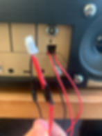
This is the cable terminal connecting into the amplifier board:

And this is the cable setup on the Raspberry Pi end:


One final sanity check by plugging in the cable we just made to both boards, and we can use the multimeter (if you have one, to be honest this is a pretty handy tool to have) and place one lead on the USB housing of the amplifier board and the other lead on the Ethernet housing of the Raspberry Pi. If it comes out to 0 then we know everything is hooked up!

Now the moment of truth…before you plug the board back into the unit, plug in the battery back into the amplifier board and turn the volume control on. If you see the lights on the Raspberry Pi turn on, you know you’ve done it!
Step 8: Putting It All Together!
All the work you’ve done has led to this point. We finally get to put it all back together! After you’ve removed all the supports from your 3D printed back plate, unscrew the left speaker completely and the two screws closest to the middle of the right speaker. The back plate attaches to the back of the unit with the included screws used for the speaker. It may be a tight fit, but you can do it!


Once that is all snug, reinsert the amplifier board onto the standoffs. I then cut a small hole right below the lightning bolt to feed the power for the Raspberry Pi through. I made the hole a little bigger than needed so I could feed a few more wires through from GPIO pins to BeatBox buttons, if I wanted to control other functions on the Pi directly with BeatBox buttons in the future.
Then, screw the Raspberry Pi to the screen mount with 4, M3 screws. Once secured, screw the mount to the back plate with M4 screws and hex nuts. The last step is the then to attach the screen with M3 screws.


Once everything is plugged back in, the last step is to turn on the Beatbox. If everything worked, then you should have the Android home screen in front of you! Fire up the Rhythmo app and have at it! Congrats!!! Post your creation to show off your work and tag us!

Optional: Power and Volume Control
One downside is that the Raspberry Pi's volume control isn’t controlled by the Beatbox, and you kind of need the volume to be on max for the BeatBox speakers to work properly. One way around this though is by going into the settings and under System > Advanced Settings, there is an option to enable a power button on GPIO 21 and volume control on GPIO 20 and 26. By referring to the Raspberry Pi GPIO diagram, you can connect a button between those pins and ground to be able to control volume levels and power.
Another way of doing this is by dragging the screen down from the right corner to reveal the notification window. From here, drag bar down where the WIFI symbol is and click the button in the bottom left corner. From here you can scroll down and click and hold the speaker to be able to drag it to the top. This adds volume control from the notification panel.

